
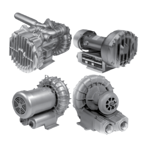
Regenair regenerative blowers
Regenair regenerative blowers are a type of industrial blower that uses a unique operating principle to move air or other gases. These blowers are designed to deliver high volume, low-pressure airflow, and are commonly used in applications such as wastewater treatment, pneumatic conveying, vacuum lifting, and other industrial processes that require the movement of air or gas.
Regenair® blowers work by utilizing the regenerative principle, which involves a spinning impeller that generates a high-velocity airflow that is directed into a stationary stator. As the air passes through the stator, it is redirected back into the impeller, where it is compressed and forced out through the discharge port. This cycle of compression and expansion creates a continuous flow of air or gas.
One of the main advantages of Regenair® blowers is their efficiency. They are able to achieve high flow rates with relatively low power consumption, making them an energy-efficient option for many industrial applications. They are also compact, durable, and require minimal maintenance, making them a popular choice for a wide range of industries.
Overall, Regenair® regenerative blowers are a reliable and cost-effective solution for many industrial applications that require the movement of air or gas.
Why use a Regenair ® Regenerative Blower?
Features and Benefits
- Rugged construction of cast aluminum or cast iron, depending on model size
- UL and CSA approved motors; TEFC on single-
ended models, OPEN on dual-ended models.
Permanently sealed ball bearings incorporate new
polyurea grease that extends bearing life and offers
superior resistance to washout, rust, and corrosion.
Integrated mufflers on single-ended models
minimize operating noise
- UL and CSA approved explosion-proof multi-voltage motors with thermal protection
- Double sealed ball bearings with a B10 life exceeding 30,000 hours of continuous operation at the maximum rated continuous blower load
- Sealed air streams; leak tested to less than 5 cc/min
- Drive pulley size can be changed to lower speeds and adjust performance
- Built-in acoustical muffling reduces operation noise
- Precision balanced impellers provide low vibration operation
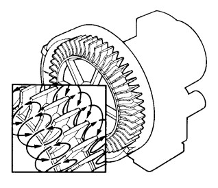
The Regenerative Principle
In a regenerative blower, the compression space consists of a hollow,
circular ring between the tips of the impeller blades and the walls of the
housing. In operation, the rotating impeller draws in air from the inlet
port into the compression space and moves it radially outward to the
curved housing by centrifugal force.
The action is called “regenerative” because a certain amount of air
slips past each impeller blade during rotation and returns to the base
of a succeeding blade for reacceleration.
Because of this dynamic principle, regenerative blowers can generate
pressure and vacuum performance comparable to many multi-stage or
positive displacement blowers.
Regenair ® Regenerative Blowers Performance Overview
| MODEL/ SERIES |
POWER RATING @ 60 Hz |
FREE AIR FLOW | MAXIMUM PRESSURE | MAXIMUM VACUUM | ||||||||||
|---|---|---|---|---|---|---|---|---|---|---|---|---|---|---|
| CFM | M³/h | inH₂O | mbar | inH₂O | mbar | |||||||||
| HP | Kw | 50 Hz | 60 Hz | 50 Hz | 60 Hz | 50 Hz | 60 Hz | 50 Hz | 60 Hz | 50 Hz | 60 Hz | 50 Hz | 60 Hz | |
| Standard Motor Mounted Models | ||||||||||||||
| R1* | ¹/₈ | 0,09 | 23 | 27 | 39 | 46 | 21 | 28.5 | 52 | 71 | 20 | 26.5 | 50 | 66 |
| R2* | ¹/₃ ,¹/₂ | 0,25,0,37 | 33 | 42 | 56 | 71 | 30 | 39 | 75 | 97 | 25 | 35 | 62 | 87 |
| R3* | ¹/₂ | 0,37 | 43-44 | 52-53 | 73-75 | 88-90 | 31-40 | 43-55 | 77-100 | 107-137 | 28-35 | 40-50 | 70-87 | 100-125 |
| R4* | 1 | 0,75 | 75 | 92 | 127 | 156 | 38 | 52 | 95 | 130 | 35 | 45 | 87 | 120 |
| R4P* | 1¹/₂ | 1,1 | 110 | 127 | 187 | 216 | 50 | 65 | 125 | 162 | 45 | 60 | 112 | 149 |
| R5* | 2¹/₂ | 1,86 | 133 | 160 | 226 | 272 | 50 | 65 | 125 | 162 | 47 | 60 | 117 | 149 |
| R6* | 2¹/₂- 5 |
1,86- 3,73 |
180 | 207- 215 |
306 | 352- 365 |
40- 78 |
45- 105 |
100- 194 |
112- 262 |
50- 70 |
55- 88 |
125- 194 |
137- 262 |
| R6P* | 3¹/₂- 5¹/₂ |
2,6- 4,1 |
225- 245 |
265- 290 |
382- 416 |
450- 493 |
50- 85 |
30- 110 |
125- 212 |
75- 274 |
50- 85 |
35- 90 |
126- 212 |
87- 224 |
| R6PP* | 11 | 8,2 | 420 | 520 | 714 | 884 | 75 | 95 | 187 | 237 | 65 | 80 | 162 | 199 |
| R7* | 10 | 7,46 | 350 | 420 | 595 | 714 | 115 | 125 | 286 | 311 | 90 | 110 | 224 | 274 |
| R7P* | 18 | 13,4 | 666 | 795 | 1132 | 1351 | 90 | 105 | 284 | 262 | 85 | 95 | 212 | 237 |
| R9* | 15 | 11,3 | 585 | 680 | 994 | 1155 | 125 | 125 | 311 | 311 | 105 | 115 | 262 | 286 |
| R9P* | 30 | 22,4 | 1140 | 1350 | 1937 | 2294 | 110 | 125 | 274 | 311 | 100 | 110 | 249 | 274 |
| High Pressure Motor Mounted Models | ||||||||||||||
| R4H* | 6 | 4,5 | 107 | 128 | 182 | 217 | 284 | 284 | 707 | 707 | 183 | 183 | 456 | 456 |
| R6PS* | 11 | 8,2 | 230 | 280 | 391 | 476 | 145 | 170 | 261 | 423 | 110 | 130 | 274 | 324 |
| R7S* | 18 | 13,4 | 350 | 420 | 595 | 714 | 170 | 200 | 423 | 498 | 130 | 150 | 324 | 374 |
| R9S* | 30 | 22,4 | 585 | 660 | 994 | 1121 | 208 | 222 | 518 | 553 | 142 | 149 | 354 | 371 |
| Explosion Proof Motor Models | ||||||||||||||
| R3105N-50 | ¹/₂ | 0,37 | 44 | 53 | 75 | 90 | 31 | 43 | 77 | 107 | 28 | 40 | 70 | 100 |
| R4110N-50 | 1 | 0,75 | 74 | 92 | 126 | 156 | 38 | 51 | 95 | 127 | 35 | 48 | 87 | 120 |
| R4310P-50 | 1 | 0,75 | 74 | 92 | 126 | 156 | 38 | 51 | 95 | 127 | 35 | 48 | 87 | 120 |
| R4P115N-50 | 1¹/₂ | 1,1 | 112 | 133 | 190 | 226 | 45 | 65 | 112 | 162 | 40 | 60 | 100 | 149 |
| R5125Q-50 | 2 | 1,5 | - | 160 | - | 272 | - | 55 | - | 137 | - | 60 | - | 149 |
| R5325R-50 | 2 | 1,5 | 133 | 160 | 226 | 272 | 50 | 65 | 125 | 162 | 47 | 65 | 117 | 162 |
| R6130Q-50 | 3 | 2,2 | 180 | 215 | 306 | 365 | 75 | 60 | 187 | 149 | 65 | 70 | 162 | 174 |
| R6340R-50 | 4 | 3,0 | 180 | 215 | 306 | 365 | 75 | 100 | 187 | 249 | 65 | 80 | 162 | 199 |
| R6P155Q-50 | 5¹/₂ | 4,1 | 280 | 280 | 399 | 476 | 80 | 95 | 199 | 237 | 65 | 85 | 162 | 212 |
| R6P355R-50 | 6 | 4,5 | 280 | 280 | 394 | 476 | 80 | 100 | 199 | 249 | 65 | 85 | 162 | 212 |
| R7100R-50 | 10 | 7,5 | 425 | 425 | 595 | 722 | 90 | 100 | 224 | 249 | 85 | 110 | 212 | 274 |
| Separate Drive Models | ||||||||||||||
| SDR4 | 4 | 3,0 | 147 | 250 | 110 | 274 | 90 | 224 | ||||||
| SDR5 | 10 | 7,5 | 240 | 408 | 152 | 379 | 120 | 299 | ||||||
| SDR6 | 15 | 11,2 | 300 | 510 | 155 | 386 | 135 | 336 | ||||||
*Models equipped with UL and CSA certified motors. (except R1102K (12v DC))
Catalog Performance Specifications
Blower System Design Tips
In order to utilize your regenerative blower most efficiently, proper system design is essential. The most important thing to recognize is that by utilizing large diameter plumbing, friction losses in plumbing can be greatly reduced. Here are some guidelines to use when setting up your blower system:
1. The plumbing should at least be the same size as the blower port or ideally one size larger (example – blower has ports that are 1-1/2” NPT, plumbing should be 2” NPT). The plumbing should remain this size until it has reached the location of the work area.
2. Plumbing for Separate Drive Blowers operating above 3500 RPM should be at least one pipe size larger than the blower ports.
3. Elbows create additional friction, which causes pressure loss and back pressure. Plumbing at least one pipe size larger than the blower pipe ports minimizes the friction loss they create.
4. The pressure/vacuum relief valve should be installed in a “T” which is at least one pipe size larger than that of the exhaust of the blower. To properly protect a large horsepower blower, set the relief value to limit the blowers duty to 5 in H₂O below its continuous duty rating.
5. Operating the blowers at high altitude decreases their maximum pressure or vacuum duty rating. If this is a consideration, review the information on Fan Laws in the Application Engineering section of this catalog.
6. The exhaust air temperature of the blowers increases with increasing duty. At duties over 70 in H₂ it is too hot for most plastic pipe. Metal pipe must be considered. To prevent danger of burns, access to these pipes should be limited, guarded, or marked “Danger Hot.”
The performance data shown in this catalog was determined under the following conditions:
- Line voltage @ 60 Hz 230V or 460V for three-phase units.
- 115V or 230V for single-phase units.
- Line voltage @ 50Hz 220V for three-phase or single – phase units.
- Units in a temperature stable condition.
- Delivery measurements made with output port throttled.
- Suction measurements made with input port throttled.
- Test Conditions: Inlet air density at 0.075 lbs per cu ft.
- [20 °C (68 °F), 29.92 inHg (14.7 PSIA)].
- Normal performance variations on the resistance curve within ± 10% of supplied data can be expected.
Typical Applications – Imagine what you can do with air, then call Gast
PRESSURE APPLICATIOS
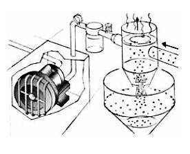
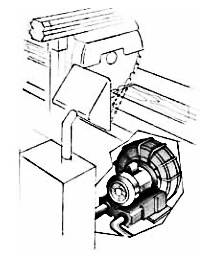
Vacuum is often used to open,
hold, and close bags in filling machines.
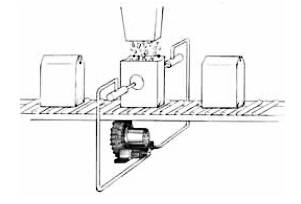
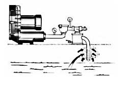
Plastic pellets, grain, powder, and other bulk dry materials can be transported from one container to another easily using vacuum. They are pulled into a transport tube and delivered to a separator before being deposited
in the final storage container.
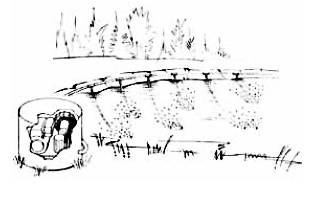
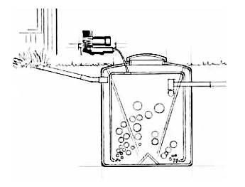
Pond aeration is done for two basic reasons. One is aquaculture, where large numbers of fish are “farmed” in a single pond. The second is ecological.
As a pond or lake ages, it can lose its oxygen supply and may die. When air is introduced into a pond or lake, oxygen becomes plentiful again and life in and around the water can flourish.
- Aquaculture/pond aeration
- Fish hatchery equipment
- Suspension systems, tire inflators
- Medical and dental sterilizing equipment
- Dental vacuum ovens, dental aspiration
- Fiberglass choppers
- Liquid/hydraulic pump drives
- Industrial cleaning equipment
- Chip removal/parts blow off
- Engraving machinery
- Lift tables
- Pneumatic conveying systems and drives
- Automated assembly machines/robotics
- Envelope opening/inserting/labeling equipment
- Document scanning equipment
- Folders, presses, counters
- Photo processing equipment
- Corrugated cutting/printing equipment
- Ink jet printer/post press printing equipment
- Collating/inserting equipment
- Ink drying equipment
- Air table
- Spa and hot tub aeration, aquarium aeration
- Handicap tub door seals, boat/pond deicing
- Ice cream/yogurt/frosting dispensers
- Pharmaceutical manufacturing equipment
- Automated food preparation equipment
- Cable pressurization/cable slicing equipment
- Circuit board processing equipment
- Air/water purifiers
- Gas generators (ozone, nitrogen)
- Sewage treatment
- Smoke evacuation
- Pest control equipment
- Soil/groundwater remediation equipment
- Marking/labeling equipment
- Filling equipment
- Food packaging/bag making equipment
- Can/bottle making equipment
- Liquid packaging equipment
- Corrugated sheet making equipment
- Sewing machine equipment, scrap collection equipment
- Mixing equipment
- Vibrators/tumblers
- Plating tank agitation
- Laundry equipment
- Forming equipment
- Parts washers/parts drying equipment/air knives
- Plastic pellet drying/conveying
- Oil atomization, industrial burners
- Texture spraying, concrete aeration
VACUUM APPLICATIONS
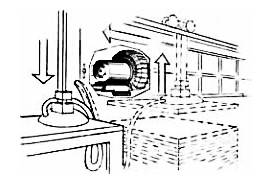
Vacuum force is used to automatically stack product as it is received or to move the product from one process to another.
Some parts of the country where city sewerage is not available and high water tables exist, household waste must be treated aerobically. This means air is mixed into a solution which activates microbes that feed on the waste, speeding up the naturally occurring organic breakdown.
- Inoculation equipment
- Dental vacuum ovens, dental aspiration
- Gas reclaiming equipment
- House air/vacuum
- Industrial vacuum systems
- Industrial cleaning equipment
- Vacuum table/hold down
- Dust collection equipment
- Chip removal
- Engraving machinery
- Vacuum hoist
- Pneumatic conveying systems
- Pneumatic tube systems
- Automated assembly machines
- Envelope opening/inserting/labeling equipment
- Vacuum feed, document scanning equipment
- Folders, presses
- Vacuum frames
- Photo processing equipment
- Paper counters
- Camera/exposure equipment
- Corrugated cutting/printing equipment
- Collating equipment
- Inserting equipment
- Post press printing equipment
- Pharmaceutical manufacturing equipment
- Automated food preparation equipment
- Electronics and communications equipment
- Circuit board processing equipment
- Cable splicing equipment
- Air sampling/monitoring equipment
- Toilet systems
- Fume extraction
- Vapor recovery
- Smoke evacuation
- Pest control equipment
- Soil vapor extraction
- Weather prediction equipment
- Case erectors/packers
- Marking/labeling equipment
- Bag making equipment
- Filling equipment
- Food packaging equipment
- Can/bottle making equipment
- Liquid packaging equipment
- Corrugated sheet making equipment
- Packing fill removal equipment
- Sewing machine equipment
- Scrap collection equipment
- Garment vacuum tables
- Trim removal
- Vibrators/tumblers, non-medical lab equipment
- Forming equipment, plastic pellet drying/conveying
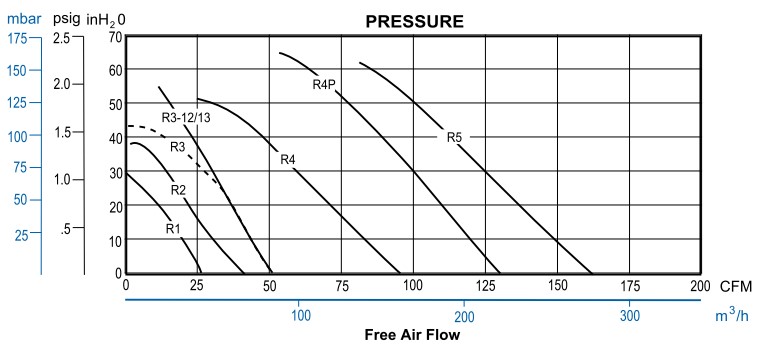
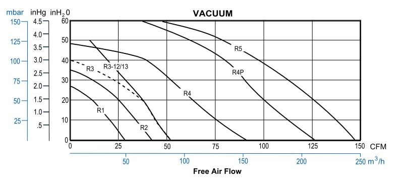
Performance Curves REGENAIR ® Regenerative Blowers
Performance Curves – Low Range for Pressure/Vacuum
Motor mounted series R1, R2, R3, R4, R4P, R5
Performance at 60 Hz
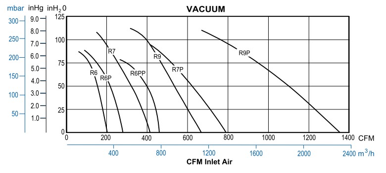
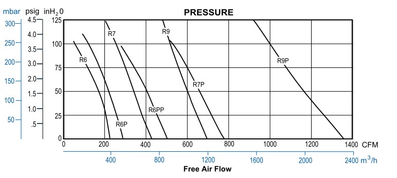
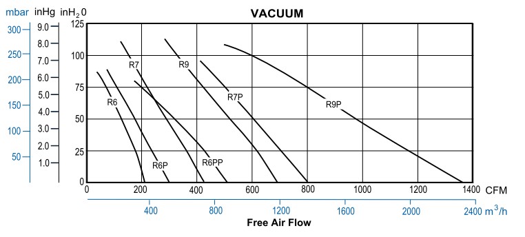
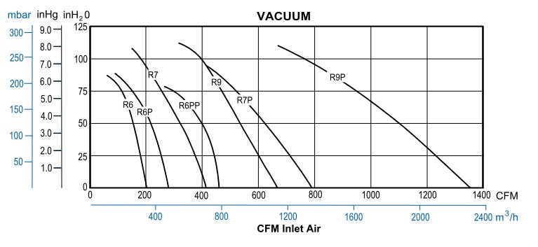
Performance Curves REGENAIR ® Regenerative Blowers
Performance Curves – Mid Range for Pressure/Vacuum
Motor mounted series R6, R6P, R6PP, R7, R7P, R9, R9
Performance at 60 Hz
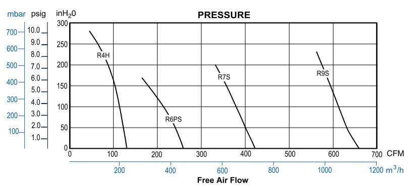
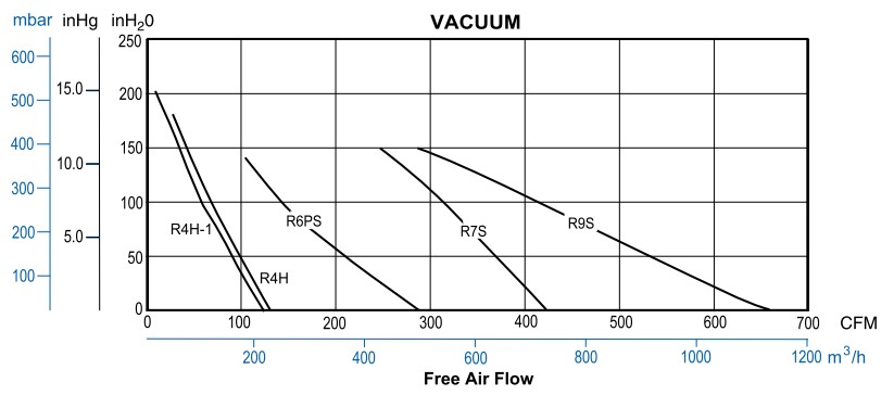
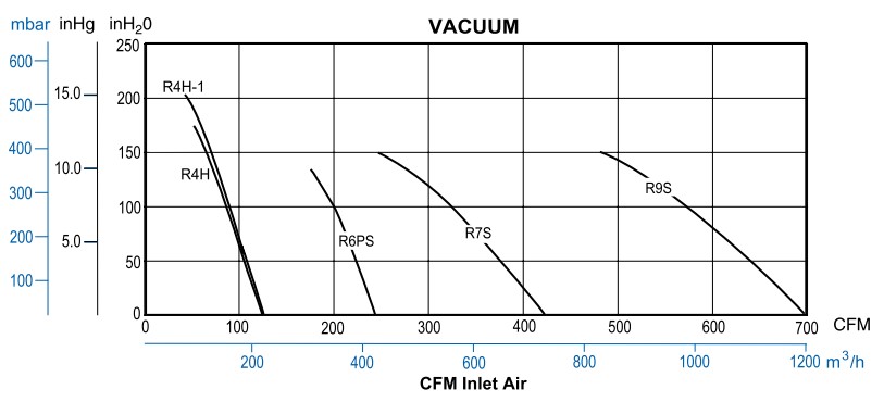
Performance Curves REGENAIR ® Regenerative Blowers
Performance Curves – High Range for Pressure/Vacuum
Motor mounted series R4H, R4H-1, R6PS, R7S, R9S
Performance at 60 Hz
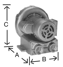
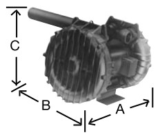
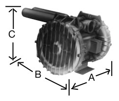
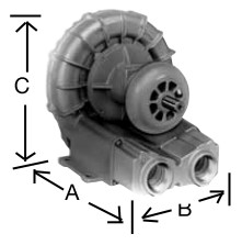
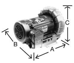
Envelope Dimensions REGENAIR ® Regenerative Blowers
| Model # | Net Wt. (lbs) |
A Length (inches) |
B Width (inches) |
C Height (inches) |
Inlet/Outlet Connections |
|
|---|---|---|---|---|---|---|
| STANDARD MOTOR MOUNTED | ||||||
| R1102 | 16 | 8.86 | 7.80 | 8.51 | 1'' | |
| R1102C | 16 | 8.86 | 7.80 | 8.51 | 1'' | |
| R1102K | 16 | 9.21 | 7.80 | 8.51 | 1'' | |
| R2103 | 21 | 9.90 | 8.93 | 9.29 | 1'' | |
| R2105 | 23 | 10.57 | 8.93 | 9.29 | 1'' | |
| R2303A | 23 | 9.90 | 8.93 | 9.29 | 1'' | |
| R2305B | 23 | 10.85 | 8.93 | 9.29 | 1'' | |
| R3105-1 | 29 | 10.94 | 9.72 | 10.15 | 1¹/₄'' | |
| R3105-12 | 29 | 10.94 | 9.72 | 10.15 | 1¹/₄'' | |
| R3305A-1 | 29 | 10.94 | 9.72 | 10.15 | 1¹/₄'' | |
| R3305A-13 | 29 | 10.94 | 9.72 | 10.15 | 1¹/₄'' | |
| R4110-2 | 41 | 12.82 | 11.25 | 11.80 | 1¹/₂'' | |
| R4310A-2 | 41 | 12.82 | 11.25 | 11.80 | 1¹/₂'' | |
| R4310B-1 | 41 | 12.82 | 11.25 | 11.80 | 1¹/₂'' | |
| R4P115 | 61 | 15.46 | 13.26 | 13.61 | 1¹/₂'' | |
| R4P315A | 43 | 11.38 | 13.26 | 13.61 | 1¹/₂'' | |
| R5125-2 | 76 | 16.14 | 13.56 | 13.80 | 1¹/₂'' | |
| R5325A-2 | 65 | 15.23 | 13.56 | 13.80 | 1¹/₂'' | |
| R5325B-1 | 65 | 14.73 | 13.56 | 13.80 | 1¹/₂'' | |
| R6125-2 | 87 | 16.45 | 15.17 | 15.38 | 2" | |
| R6325A-2 | 76 | 15.53 | 15.17 | 15.38 | 2" | |
| R6135J-10 | 112 | 15.86 | 15.17 | 15.38 | 2" | |
| R6335A-2 | 82 | 16.59 | 15.17 | 15.38 | 2" | |
| R6335B | 82 | 16.00 | 15.17 | 15.38 | 2" | |
| R6150J-2 | 125 | 17.46 | 15.17 | 15.38 | 2" | |
| R6350A-2 | 112 | 17.35 | 15.17 | 15.38 | 2" | |
| R6350B-2 | 112 | 17.35 | 15.17 | 15.38 | 2" | |
| R6P335A | 150 | 16.69 | 16.75 | 18.15 | 2" | |
| R6P350A | 176 | 17.75 | 16.75 | 18.15 | 2" | |
| R6P350B | 176 | 17.75 | 16.75 | 18.15 | 2" | |
| R6P355A | 215 | 19.92 | 16.75 | 18.15 | 2" | |
| R6PP3110M | 309 | 23.19 | 16.75* | 18.21 | 2"/3'' | |
| R7100A-3 | 293 | 22.58 | 18.00 | 20.03 | 2¹/₂'' | |
| R7100B-1 | 290 | 21.58 | 18.00 | 20.03 | 2¹/₂'' | |
| R7P3180M | 438 | 28.47 | 18.00* | 20.12 | 2¹/₂''/4'' | |
| R93150A | 452 | 26.13 | 20.63 | 22.63 | 3'' | |
| R9P3300M | 622 | 32.78 | 20.63* | 22.54 | 3''/5'' | |
| HIGH PRESSURE MODELS | ||||||
| R4H3060A | 200 | 21.47 | 16.90 | 18.82 | 2" | |
| R4H3060A-1 | 200 | 21.47 | 16.90 | 18.82 | 2" | |
| R6PS3110M | 309 | 23.19 | 16.75 | 18.21 | 2" | |
| R7S3180M | 431 | 28.47 | 18.00 | 20.12 | 2¹/₂'' | |
| R9S3300M | 606 | 32.78 | 20.63* | 22.54 | 3'' | |
| EXPLOSION PROOF MOTOR MODELS | ||||||
| R3105N-50 | 52 | 12.3 | 12.75 | 10.15 | 1¹/₄'' | |
| R4110N-50 | 60 | 15.34 | 12.34 | 11.80 | 1¹/₂'' | |
| R4310P-50 | 58 | 14.09 | 12.34 | 11.80 | 1¹/₂'' | |
| R4P115N-50 | 79 | 17.41 | 13.75 | 13.61 | 1¹/₂'' | |
| R5125Q-50 | 77 | 17.59 | 13.72 | 13.80 | 1¹/₂'' | |
| R5325R-50 | 75 | 16.75 | 13.56 | 13.80 | 1¹/₂'' | |
| R6130Q-50 | 129 | 18.97 | 15.17 | 15.34 | 2" | |
| R6340R-50 | 112 | 18.82 | 15.17 | 15.31 | 2" | |
| R6P155Q-50 | 243 | 22.81 | 16.75 | 18.14 | 2" | |
| R6P355R-50 | ||||||
| R7100R-50 | 297 | 22.77 | 18.00 | 20.03 | 2¹/₂'' | |
| SEPARATE DRIVE MODELS | ||||||
| SDR4 | 27 | 12.44 | 11.25 | 11.80 | 1¹/₂'' | |
| SDR5 | 37 | 14.22 | 13.56 | 13.78 | 1¹/₂'' | |
| SDR6 | 70 | 15.89 | 15.17 | 15.31 | 2'' | |
*Less muffler(s)
R1, R2, R3, R4, R4H, R4P, R5, R6, R6P, R7, R9
R3, R4, R4P, R5, R6, R6P, R7
Accessories REGENAIR ® Regenerative Blowers
Mufflers
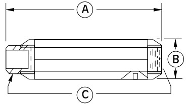
| Part No. | Dim. A | Dim. B | Dim. C | Used On |
|---|---|---|---|---|
| AJ121B | 7.46'' | 2.38'' | 1'' NPT | R1, R2 |
| AJ121C | 7.94'' | 2.62'' | 1¹/₄'' NPT | R3 |
| AJ121D | 12.75'' | 3.25'' | 1¹/₂'' NPT | R4, R5, R4P, R4H, R7 |
| AJ121F | 17.05'' | 3.63'' | 2'' NPT | R4H, R6, R6P, R6PP, R6PS |
| AJ121G | 17.44'' | 4.25'' | 2¹/₂'' NPT | R7, R7P, R7S |
| AJ121H | 20.25'' | 4.75'' | 3'' NPT | R6PP (Exhaust), R9, R9P, R9S |
| AJ121M | 33.50'' | 6.00'' | 4'' NPT | R7P (Exhaust) |
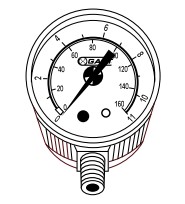
Pressure-Vacuum Gauge
| Part No. | Used On | |||||||||
|---|---|---|---|---|---|---|---|---|---|---|
| AJ497 | Vacuum gauge | 0-60 inH₂O, 1/4'' NPT connection | R1, R2, R3, R4 R4H, R4P, R5, R7, R7P, R7S, R9, R9P, R9S | |||||||
| AE134 | Vacuum gauge | 0-160 inH₂O, 1/4” NPT connection | R4P, R6PP, R6PS, R6P, R4M, R6, R7, R7S, R7P, R9, R9P, R9S | |||||||
| AE134F | Vacuum gauge | 0-15 inHg, 1/4” NPT connection | R4H, | |||||||
| AE133 | Pressure gauge | 0-160 inH₂O, 1/4” NPT connection | R6PP, R6P, R5, R4P, R6, R7P, R9, R9P | |||||||
| AE133A | Pressure gauge | 0-200 inH₂O, 1/4” NPT connection | R6PS, R7, R7S | |||||||
| AE133F | Pressure gauge | 0-15 psi, 1/4” NPT connection | R4H, R9S | |||||||
| AJ496 | Pressure gauge | 0-60 inH₂O, 1/4” NPT connection | R1, R2, R3, R4 | |||||||
Check Valve
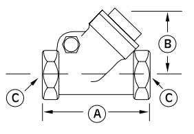
| Part No. | Dim. A | Dim. B | Dim. C |
|---|---|---|---|
| AH326B | 3.57'' | 2.32'' | 1'' NPT |
| AH326C | 4.19'' | 2.69'' | 1¹/₄'' NPT |
| AH326D | 4.50'' | 2.94'' | 1¹¯/₄'' NPT |
| AH326F | 5.25'' | 3.82'' | 2'' NPT |
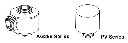
Relief Valve
By setting a relief valve at a given pressure/vacuum, you can ensure excessive duties will not harm the blower or products in your application.
| Part No. | Used On | ||||||
|---|---|---|---|---|---|---|---|
| AG258 | Relief Valve | 1-1/2'' NPT adjustable 30-200 inH₂O, vac. or press., 200 CFM max. | |||||
| AG258F | Relief Valve | 2-1/2” NPT adjustable 25-200 inH₂Os, vacuum or pressure, 570 CFM | |||||
| PV102 | Relief Valve | For pressure, pre-set for 10.2 psi, 1-1/4'' NPT connection (60 Hz) | |||||
Filters
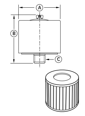
Inlet filters (for pressure)
| Part No. | Dim. A | Dim. B | Dim. C | Filter Replacement | Used On | |||
|---|---|---|---|---|---|---|---|---|
| AJ126B | 6.00'' | 4.62'' | 1'' MPT | AJ134B (10 micron) | R1, R2 | |||
| AJ126C | 6.00'' | 7.12'' | 1¹/₄'' MPT | AJ134C (10 micron) | R3 | |||
| AJ126D | 7.70'' | 7.25'' | 1¹/₂'' MPT | AJ134E (10 micron) | R4, R4H, R4P, R5 | |||
| AJ126F | 10.63'' | 4.81'' | 2'' MPT | AG340 (10 micron) | R6, R6P, R6PS, R6PP, R9 | |||
| AJ126G | 10.00'' | 13.12'' | 2¹/₂'' MPT | AJ135A (10 micron) | R7, R7P, | |||
| AJ126L | 10.00'' | 14.62'' | 4'' MPT | AJ135C (10 micron) | Consult factory | |||
| AJ126M | 16.00'' | 14.62'' | 5'' MPT | AJ135H (10 micron) | Consult factory | |||
MPT = male Pipe Thread. FPT = Female Pipe Thread. All are heavy-duty for high amounts of particulates.
Inlet filters for REGE nAIR ® blowers are drip-proof when mounted as shown.
Filters
In locations where there are high amounts of dust, powder, or dirt suspended in the air, inline filters (for vacuum applica – tions) and inlet filters
(pressure applications), should be used. Keeping particulates from entering the blower will ensure smooth operation and trouble free service life.
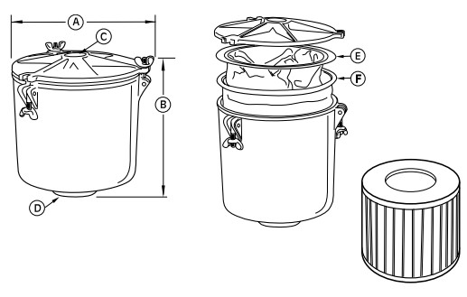
Inline filters (for vacuum)
AV series
| Part No. | Dim. A | Dim. B | Dim. C | Dim. D | Used On |
|---|---|---|---|---|---|
| AV460 | 8¹/₄'' | 8⁷/₈'' | 1'' FPT | 1'' FPT | R1, R2 |
| AV460C | 8¹/₄'' | 8⁷/₈'' | 1¹/₄'' FPT | 1¹/₄'' FPT | R3 |
Replacement elements for AV460 and AV460C:
AV463A - Cloth bag, 50 micron, sold in 3 pack (letter F on diagram).
AV469A - Paper filter, 5-10 micron, sold in 12 pack (letter E on diagram).
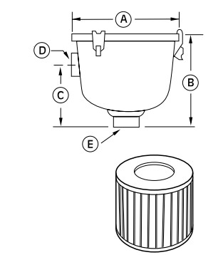
AJ series
| Part No. | Dim. A | Dim. B | Dim. C | Dim. D | Dim.E | Filter Replacement | Used On |
|---|---|---|---|---|---|---|---|
| AJ151A | 5.88'' | 4.50'' | 2.75'' | 1'' FPT | 1'' FPT | AJ135D (10 micron) | R1 |
| AJ151B | 7.38'' | 6.81'' | 4.62'' | 1'' FPT | 1'' FPT | AJ135E (10 micron) | R2 |
| AJ151C | 7.38'' | 6.81'' | 4.62'' | 1¹/₄'' FPT | 1¹/₄'' FPT | AJ135E (10 micron) | R3 |
| AJ151D | 7.38'' | 6.81'' | 4.62'' | 1¹/₂'' FPT | 1¹/₂'' FPT | AJ135E (10 micron) | R4, R4P |
| AJ151E | 8.75'' | 10.25'' | 5.00'' | 2'' FPT | 2'' FPT | AJ135F (10 micron) | R4H, R4P, R5 |
| AJ151G | 8.75'' | 10.50'' | 5.50'' | 2¹/₂'' FPT | 2¹/₂'' FPT | AJ135G (10 micron) | R6, R6P |
| AJ151H | 14.00'' | 27.13'' | 18.50'' | 3'' MPT | 3'' MPT | AJ135C (10 micron) | R6PP, R6PS, R7 |
| AJ151M | 18.50'' | 28.13'' | 19.50'' | 5'' MPT | 5'' MPT | AJ135H (10 micron) | R7P, R7S, R9, R9P, R9S |
mPT = male Pipe Thread. FPT = Female Pipe Thread. All are heavy-duty for high amounts of particulates.
Inline filters for REGE nAIR ® blowers are drip-proof when mounted as shown.
Regenair ® Filter Restrictions with Clean Element
Inlet Filters
| Blower | Filter | Restriction in inH₂O at CFM Flow Indicated |
|
|---|---|---|---|
| R1 | AJ126B | 2.2'' @ 27 CFM | |
| R2 | AJ126B | 4.5'' @ 40 CFM | |
| R3 | AJ126C | 2.5'' @ 50 CFM | |
| R4H | AJ126D | 8'' @ 120 CFM | |
| R4 | AJ126D | 4'' @ 85 CFM | |
| R4P | AJ126D | 8'' @ 120 CFM | |
| R5 | AJ126D | 11'' @ 146 CFM | |
| R6 | AJ126F | 7'' @ 200 CFM | |
| R6P/R6PS | AJ126F | 11'' @ 265 CFM | |
| R6PP | (2) AJ126F | 10'' @ 240 CFM | |
| R7/R7S | AJ126G | 12'' @ 400 CFM | |
| R7P | (2) AJ126G | 12'' @ 400 CFM | |
| R9S | AJ126M | Consult factory | |
| R9P | AJ126M | Consult factory | |
Inlet Filters
| Blower Size |
Filter Number |
Restriction in inH₂O at CFM Flow Indicated |
|
|---|---|---|---|
| R1 | AJ151A | 1'' @ 25 CFM | |
| AV460 | 2'' @ 25 CFM | ||
| R2 | AJ151B | 2'' @ 40 CFM | |
| AV460 | 5'' @ 40 CFM | ||
| R3 | AJ151C | 2'' @ 50 CFM | |
| AV460C | 3'' @ 50 CFM | ||
| R4 | AJ151D | 3'' @ 100 CFM | |
| R4P | AJ151E | 3'' @ 100 CFM | |
| R4H | AJ151E | 3'' @ 120 CFM | |
| R5 | AJ151E | 4'' @ 160 CFM | |
| R6 | AJ151G | 2'' @ 200 CFM | |
| R6P/R6PS | AJ151G | 3'' @ 300 CFM | |
| 6PP | AJ151H | 8'' @ 400 CFM | |
| R9S | AJ151 M | Consult factory | |
| R9P | AJ151 M | Consult factory | |